
Miller 70 Series Wire Feeder Manual: Article Plan
This comprehensive guide details setup‚ troubleshooting‚ and maintenance for Miller 70 Series wire feeders‚ covering models like S-74S and S-74D‚ ensuring optimal welding performance․
Miller 70 Series wire feeders represent a robust and versatile solution for a wide range of welding applications․ These feeders‚ including popular models like the S-74S and S-74D‚ are renowned for their durability and reliable performance in both industrial and field settings․ Understanding the intricacies of these machines is crucial for maximizing welding efficiency and ensuring high-quality results․
This manual aims to provide a detailed overview of the Miller 70 Series‚ covering everything from initial setup and operation to troubleshooting common issues and performing essential maintenance․ It addresses concerns regarding documentation clarity‚ particularly regarding calibration and synchronization procedures‚ often noted by users․ Proper understanding of the feeder’s components‚ like drive rollers and the gun trigger circuit‚ is vital for effective use․
Common Applications & Welding Processes
Miller 70 Series wire feeders excel in diverse welding applications‚ primarily supporting MIG (GMAW) and Flux Cored (FCAW) processes․ These feeders are frequently utilized in manufacturing‚ construction‚ repair work‚ and heavy equipment fabrication․ Their adaptability allows for welding various metals‚ including steel‚ stainless steel‚ and aluminum‚ depending on the chosen wire and gas combinations․
Successful welding relies on correct setup for each process․ Issues like incorrect wire guide size or worn components can significantly impact weld quality‚ necessitating inspection and replacement․ Furthermore‚ understanding potential problems within the gun trigger circuit‚ such as a stuck-closed trigger‚ is crucial for consistent arc control and preventing operational disruptions․
2․1 MIG (GMAW) Welding with Miller 70 Series
MIG (GMAW) welding with a Miller 70 Series feeder demands precise parameter settings for optimal results․ Proper gas shielding is paramount‚ preventing oxidation and ensuring a clean weld․ Selecting the correct contact tip size‚ matching the wire diameter‚ is essential for stable arc initiation and consistent wire feed․ Regularly inspect the nozzle for spatter buildup‚ as obstructions can compromise gas coverage and weld quality․
Troubleshooting often involves verifying the gun trigger connection at the wire feeder and inspecting the trigger leads and switch for continuity․ A faulty trigger circuit can cause intermittent welding or complete failure․ Remember to consult the gun owner’s manual for specific maintenance procedures․

2․2 Flux Cored (FCAW) Welding with Miller 70 Series
Flux Cored (FCAW) welding utilizing a Miller 70 Series wire feeder requires attention to slag removal and proper technique․ Unlike MIG‚ FCAW often doesn’t necessitate external shielding gas‚ relying on the flux within the wire․ However‚ maintaining a clean welding environment remains crucial․ Inspecting and replacing worn wire guides and liners is vital‚ as buildup can impede smooth wire feeding․
Common issues include wire feeding problems‚ potentially stemming from incorrect drive roller tension or a damaged drive motor․ If the gun trigger circuit appears stuck closed‚ a Factory Authorized Service Agency should inspect the drive motor and control board (PC1) for proper function․
Spool Size and Wire Compatibility
Miller 70 Series wire feeders accommodate various spool sizes‚ typically ranging from 5 to 60 pounds‚ depending on the specific model (S-74S‚ S-74D‚ etc․)․ Compatibility extends to a wide array of wire types‚ including steel‚ stainless steel‚ and aluminum‚ each requiring appropriate drive roll selection․
Selecting the correct drive rollers is paramount for consistent feeding․ Incorrect size or worn wire guides can cause issues‚ necessitating replacement of the contact tip or liner․ Always consult the gun Owner’s Manual for specific wire diameter and type recommendations to ensure optimal welding performance and prevent potential feeding problems․
Initial Setup and Installation
Proper setup of your Miller 70 Series wire feeder is crucial for safe and efficient operation․ Begin by carefully connecting the feeder to a compatible power source‚ ensuring correct voltage settings․ Secure and reliable grounding procedures are essential to prevent electrical shock; always follow established safety guidelines․
Before initiating welding‚ verify all connections are tight and inspect the wire feed path for obstructions․ Pay attention to the board connection configurations‚ as they differ between inverter and non-inverter machines․ A thorough pre-installation check minimizes potential issues and ensures a smooth welding experience․
4․1 Connecting to Power Source
Connecting your Miller 70 Series wire feeder to the power source requires careful attention to voltage specifications․ Ensure the power source matches the feeder’s input requirements‚ typically 115V or 230V‚ as indicated on the unit’s nameplate․ Use appropriately sized cables and secure connections to prevent voltage drops and overheating․
Double-check polarity before powering on‚ referencing the manual for correct wiring diagrams․ Incorrect polarity can damage the equipment․ A stable and reliable power connection is fundamental for consistent wire feeding and arc stability during welding operations․ Always disconnect power before making any adjustments or inspections․
4․2 Grounding Procedures
Proper grounding is crucial for safety and optimal performance of your Miller 70 Series wire feeder․ Connect the feeder’s grounding terminal to a known‚ reliable earth ground using a heavy-gauge cable․ This minimizes the risk of electric shock and reduces electrical noise that can interfere with the welding arc․
Ensure the grounding connection is clean and free of corrosion for effective conductivity․ Regularly inspect the grounding cable for damage․ A well-established ground path also helps prevent damage to the machine’s internal components․ Always adhere to local electrical codes and safety regulations when implementing grounding procedures․
Understanding the Control Panel
The Miller 70 Series control panel provides essential adjustments for welding parameters․ Key controls include voltage and wire feed speed‚ allowing precise arc tuning for various materials and thicknesses․ A purge control manages shielding gas flow‚ vital for clean‚ strong welds․ Some models feature digital displays for accurate setting monitoring․
Familiarize yourself with the function of each switch and knob․ Understanding the control panel’s layout is crucial for efficient operation and troubleshooting․ Refer to your specific model’s manual for detailed explanations of each control’s impact on the welding process․ Proper adjustment ensures weld quality and minimizes defects․
Wire Feeding System Components

The Miller 70 Series wire feeding system ensures smooth and consistent wire delivery․ Core components include the drive rollers‚ which grip and propel the wire‚ and the wire guides‚ directing it towards the gun․ A crucial element is the liner‚ minimizing friction and preventing bird nesting․ Regular inspection of these parts is vital for optimal performance․
Worn or damaged drive rollers can cause inconsistent feeding‚ while clogged wire guides impede wire flow․ A damaged liner significantly increases friction‚ leading to feeding issues․ Maintaining these components prevents downtime and ensures high-quality welds․ Proper maintenance extends the lifespan of the entire system․
6․1 Drive Rollers and Wire Type Selection
Selecting the correct drive rollers is paramount for efficient wire feeding․ Miller 70 Series feeders require rollers matched to the wire diameter and type – solid wire‚ flux-cored‚ or aluminum․ Using incorrect rollers leads to slippage‚ inconsistent feeding‚ and potential bird nesting within the liner․ Drive rollers feature different knurling patterns optimized for specific wire types․
Smooth knurling suits solid wires‚ while textured rollers grip flux-cored wires effectively․ Aluminum wire demands dedicated U-groove rollers to prevent deformation․ Regularly inspect rollers for wear‚ scoring‚ or buildup․ Replacing worn rollers restores proper feeding pressure and ensures consistent weld quality․ Refer to the Miller documentation for specific wire type recommendations․
6․2 Wire Guides and Liner Maintenance
Maintaining clean and unobstructed wire guides and liners is crucial for smooth wire feeding․ Spatter‚ rust‚ or wire debris accumulation increases friction‚ causing feeding issues and weld defects․ Regularly inspect the liner for wear‚ kinks‚ or corrosion․ Replace the liner whenever signs of damage appear‚ as a compromised liner significantly hinders wire travel․
Wire guides should be free of obstructions and properly aligned․ Use compressed air to clear any buildup within the liner and guides․ Applying a wire feeding lubricant can further reduce friction‚ especially with aluminum wire․ Incorrectly sized or worn contact tips contribute to liner wear; ensure proper fit․ A well-maintained system prevents bird nesting and ensures consistent arc stability․
Troubleshooting Common Issues
Addressing issues promptly minimizes downtime and ensures consistent welding․ Common problems include erratic wire feeding‚ stemming from worn drive rolls‚ a dirty liner‚ or incorrect tension․ Gun trigger malfunctions‚ often caused by a stuck trigger circuit or faulty wiring‚ require inspection of the trigger connection at the feeder․ Nozzle blockages‚ due to spatter buildup‚ disrupt gas flow and weld quality․
If encountering these issues‚ first verify power connections and grounding․ Inspect the wire spool for proper seating and free rotation․ Consult the error code section for specific diagnostics․ For persistent problems‚ a Factory Authorized Service Agency can diagnose drive motor or control board (PC1) failures․
7․1 Wire Feeding Problems
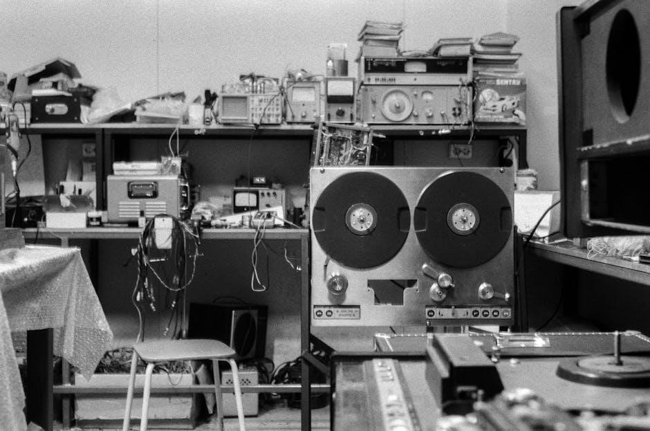
Inconsistent wire feed is a frequent issue‚ often signaled by sputtering or stopping mid-weld․ Begin by checking the drive rollers for wear or damage‚ ensuring they match the wire type․ A dirty or worn wire guide‚ or liner‚ creates friction‚ hindering smooth feeding․ Verify correct wire tension; too loose causes slipping‚ while too tight deforms the wire․
Inspect the spool for binding and ensure proper seating on the spool hub․ Remove any accumulated weld spatter around the wire path․ If problems persist‚ a faulty drive motor or control board (PC1) may require professional attention․ Always replace a worn contact tip or liner promptly․
7․2 Gun Trigger Issues & Circuit Checks
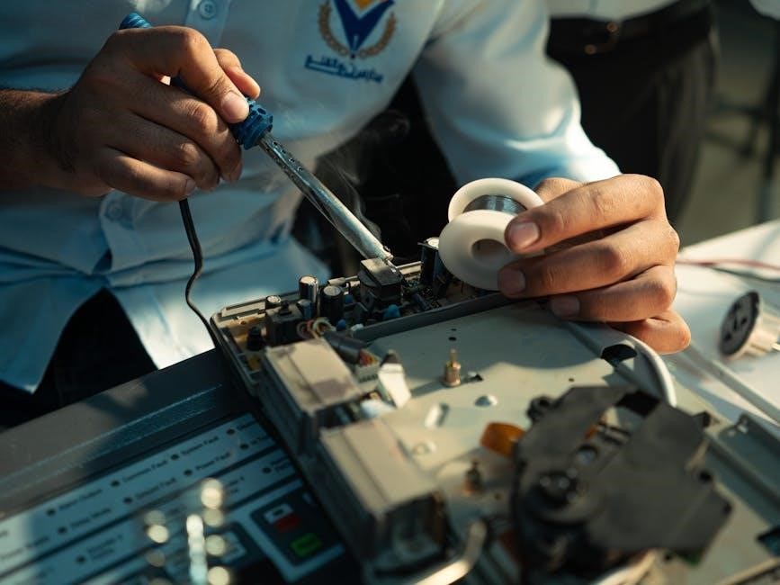
A non-responsive or erratic gun trigger often indicates a connection problem; First‚ meticulously check the gun trigger connection at the wire feeder‚ ensuring a secure fit․ Inspect the gun trigger leads and the trigger switch itself for any signs of damage‚ corrosion‚ or loose wiring․ A stuck-closed trigger circuit can also cause continuous wire feed․
Use a multimeter to verify continuity through the trigger circuit․ If the circuit shows no continuity‚ the trigger switch likely needs replacement․ If the circuit appears closed even when the trigger isn’t pulled‚ a short circuit exists․ Consult a Factory Authorized Service Agency for complex electrical issues or PC1 board diagnostics․
Error Codes and Their Meanings
Miller 70 Series wire feeders utilize error codes to diagnose internal problems․ While specific codes vary by model (S-74S‚ S-74D)‚ understanding their general meaning is crucial for efficient troubleshooting․ Common issues include drive motor faults‚ control board (PC1) errors‚ and wire feed inconsistencies․
Refer to your specific model’s owner’s manual (available at MillerWelds․com) for a complete list of error codes and their corresponding solutions․ Often‚ a code indicates a need to check the gun trigger circuit‚ wire guides‚ or contact tip․ Persistent errors may require professional diagnosis and repair by a Factory Authorized Service Agency․
Drive Motor and Control Board (PC1) Diagnostics
Diagnosing issues with the drive motor or control board (PC1) often requires a Factory Authorized Service Agency‚ as these components are complex․ However‚ preliminary checks can be performed․ Verify proper power supply and connections to both the motor and PC1․ Listen for unusual noises from the drive motor during operation – grinding or clicking sounds indicate potential failure․
If error codes point to the PC1‚ carefully inspect the board for any visible damage‚ such as burnt components․ Remember that the 60 series feeders have different board configurations for inverter versus non-inverter machines․ Always consult the owner’s manual and exercise caution when working with electrical components․

Contact Tip and Nozzle Maintenance
Regular maintenance of the contact tip and nozzle is crucial for consistent weld quality․ Inspect the contact tip for wear‚ corrosion‚ or buildup of spatter after each use․ Replace worn or damaged tips immediately to prevent erratic wire feeding․ Ensure the correct size tip is used for the wire diameter․ Similarly‚ check the nozzle for obstructions or damage․
Remove any weld spatter or foreign matter around the nozzle opening․ An incorrect size or worn wire guide can also contribute to issues‚ necessitating replacement․ Refer to the gun owner’s manual for specific instructions․ Proper maintenance extends component life and minimizes downtime․
Purge Valve Operation and Maintenance
The purge valve on Miller 70 Series feeders removes gas from the wire conduit‚ preventing bird nesting and ensuring smooth wire feeding․ Regularly inspect the purge valve for proper operation; it should activate when the trigger is released․ If the valve fails to purge effectively‚ it can lead to inconsistent welds and feeding issues․
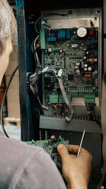
Ensure the valve isn’t obstructed by debris or corrosion․ Some models‚ like the S-32P Super‚ feature a purge valve as a key component․ Proper function is vital for maintaining gas shielding and preventing contamination; Consult the manual for specific maintenance procedures and troubleshooting steps related to the purge valve system․
Calibration and Synchronization Procedures
Proper calibration and synchronization are crucial for consistent weld quality with Miller 70 Series wire feeders․ Many users note a lack of detailed procedures in the standard manual‚ leading to frustration․ Synchronization ensures the wire feed speed matches the welding power source’s settings․ This process often involves adjusting voltage and wire feed speed parameters to achieve the desired arc characteristics․
For optimal results‚ refer to advanced resources like MillerWelds․com or consult a Factory Authorized Service Agency․ Incorrect synchronization can cause issues like erratic arc behavior and poor weld penetration․ Regularly check and adjust these settings‚ especially when changing wire types or welding processes․
Gun Connection Troubleshooting
Addressing gun connection issues is vital for smooth operation of your Miller 70 Series wire feeder․ Common problems include a faulty gun trigger circuit‚ often appearing “stuck closed‚” or intermittent wire feed․ Begin by checking the gun trigger connection at the wire feeder itself‚ ensuring a secure fit․ Inspect the gun trigger leads and the trigger switch for damage or corrosion․
If issues persist‚ consult the gun Owner’s Manual for specific troubleshooting steps․ A Factory Authorized Service Agency can diagnose more complex problems within the gun or the feeder’s control board (PC1)․ Proper connection ensures consistent power and signal transmission․
13․1 Checking Gun Trigger Connection
A secure gun trigger connection is fundamental for reliable wire feeding․ Begin by visually inspecting the connection at the wire feeder‚ ensuring the plug is fully seated and locked․ Gently wiggle the gun handle to check for any intermittent signal loss․ Disconnect and reconnect the gun to verify a clean connection‚ cleaning the pins with contact cleaner if necessary․
Pay close attention to any signs of corrosion or damage on the connector pins․ A loose or corroded connection can cause erratic wire feed or complete failure․ If the problem persists after checking the physical connection‚ proceed to inspect the gun trigger leads and switch․
13․2 Inspecting Gun Trigger Leads and Switch
Thoroughly examine the gun trigger leads for any signs of damage‚ such as cuts‚ abrasions‚ or crimped sections․ Use a multimeter to test the continuity of the leads‚ confirming a solid electrical path from the trigger switch to the wire feeder․ A broken or shorted lead will prevent proper signal transmission․
Next‚ inspect the trigger switch itself․ Operate the trigger repeatedly‚ listening for a crisp‚ positive click․ If the switch feels mushy or unresponsive‚ it may be faulty and require replacement․ A stuck-closed trigger circuit can cause continuous wire feeding‚ so prompt attention is crucial for safe operation․
Safety Precautions
Always disconnect the power source before performing any maintenance or repairs on the Miller 70 Series wire feeder․ Wear appropriate personal protective equipment (PPE)‚ including welding gloves‚ safety glasses‚ and a face shield‚ to protect against arc radiation‚ sparks‚ and fumes․ Ensure proper ventilation is available when welding to avoid inhaling harmful gases․
Never operate the wire feeder with damaged cables or connections․ Inspect the ground clamp regularly to ensure a secure connection‚ preventing electrical shock hazards․ Be mindful of moving parts‚ such as the drive rollers‚ and keep hands clear during operation․ Follow all applicable safety standards and regulations for welding equipment․
Regular Maintenance Schedule
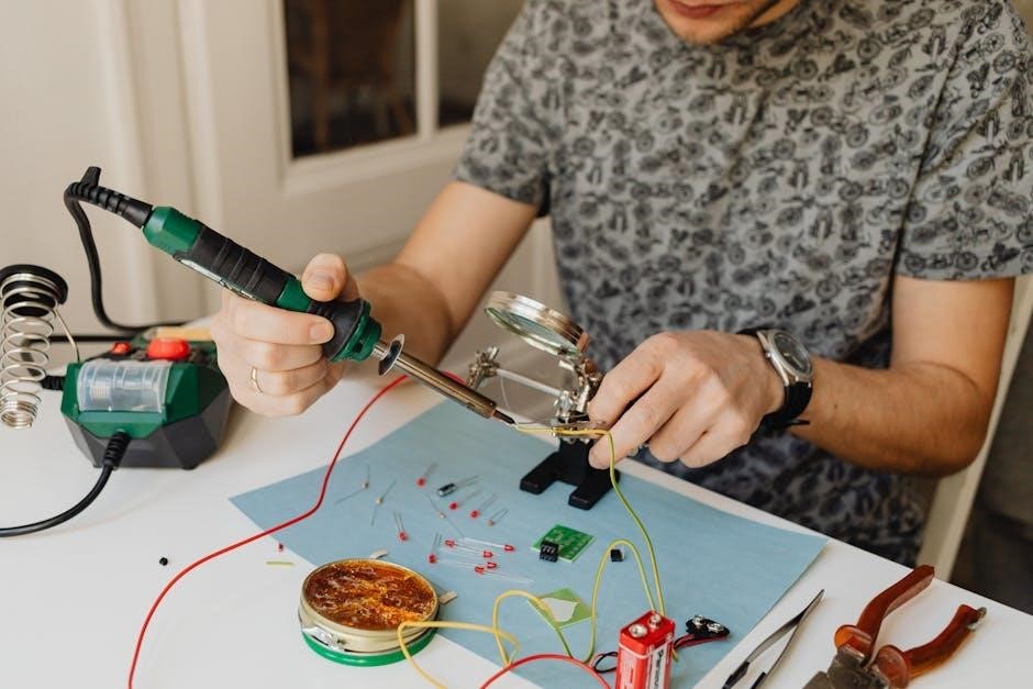
Perform daily inspections of the Miller 70 Series wire feeder‚ checking for damaged cables‚ loose connections‚ and proper gas flow․ Weekly‚ clean the wire guides and contact tip to remove accumulated weld spatter‚ ensuring smooth wire feeding․ Monthly‚ inspect and clean the drive rollers‚ replacing them if worn․
Every six months‚ thoroughly examine the wire liner for obstructions or damage‚ and replace as needed․ Annually‚ check the purge valve operation and calibrate the wire feeder to maintain accuracy․ Regularly review the owner’s manual for specific maintenance recommendations related to your model (S-74S‚ S-74D‚ etc․)․
Identifying Different 70 Series Models (S-74S‚ S-74D‚ etc․)
The Miller 70 Series encompasses several models‚ including the S-74S and S-74D‚ each designed for specific welding applications․ The S-74S is a standard wire feeder‚ while the S-74D often features enhanced digital controls and synchronization capabilities․ Identifying your specific model is crucial for accessing the correct parts and troubleshooting information․
Locate the model and serial number plate‚ typically found on the rear or side of the unit․ Refer to Miller’s documentation or website using this information to determine your feeder’s exact specifications․ Understanding these differences ensures proper setup and optimal performance for MIG (GMAW) or Flux Cored (FCAW) welding․
Inverter vs․ Non-Inverter Machine Configurations
Miller 70 Series wire feeders are compatible with both inverter and non-inverter welding power sources‚ but configuration is key․ The 60 Series feeders highlighted differing board connections based on this distinction‚ a principle extending to the 70 Series․ Inverter machines generally offer greater energy efficiency and portability․
Non-inverter machines‚ traditionally line-frequency transformers‚ are often more robust for heavy-duty applications․ Correctly identifying your power source type is vital for proper wiring and control functionality․ Incorrect configuration can lead to erratic wire feeding or complete system failure․ Consult your power source and wire feeder manuals for specific connection diagrams․
Obtaining Replacement Parts
Securing genuine Miller replacement parts is crucial for maintaining the performance and longevity of your 70 Series wire feeder․ Miller offers a comprehensive network for parts procurement․ Begin by consulting your wire feeder’s parts diagram‚ typically found within the owner’s manual or on MillerWelds․com․
Parts can be ordered directly from Miller’s website or through authorized distributors and service agencies․ Utilizing genuine Miller parts ensures compatibility and adherence to original manufacturing standards․ Avoid aftermarket alternatives‚ as they may compromise functionality or void warranty coverage․ For specialized assistance‚ contact a Factory Authorized Service Agency for expert guidance․
Factory Authorized Service Agency Information
For complex repairs‚ diagnostics‚ or when encountering issues beyond basic troubleshooting‚ a Factory Authorized Service Agency is your best resource․ These agencies employ certified technicians trained specifically on Miller welding equipment‚ including the 70 Series wire feeders․ They possess specialized tools and access to the latest technical updates․
To locate the nearest authorized service agency‚ utilize the dealer locator tool on MillerWelds․com․ This tool allows you to search by zip code or location․ Engaging a certified agency guarantees quality repairs using genuine Miller parts and ensures your equipment meets factory specifications‚ preserving its performance and warranty․

Resources and Further Information (MillerWelds․com)
MillerWelds․com serves as a central hub for comprehensive support regarding your 70 Series wire feeder․ The website hosts downloadable owner’s manuals‚ including the O235688B_MIL․pdf document‚ offering detailed setup instructions‚ troubleshooting guides‚ and parts diagrams․ Access a wealth of technical resources‚ FAQs‚ and welding tips to enhance your understanding․
Furthermore‚ MillerWelds․com provides a dealer locator to find local service agencies and distributors․ Explore online forums like WeldingWeb for community discussions and shared experiences․ Utilize the site’s contact options to directly reach Miller’s customer service for personalized assistance with your specific wire feeder needs․

